Forums
New posts
Search forums
What's new
New posts
New media
New media comments
New profile posts
Latest activity
Media
New media
New comments
Search media
Members
Current visitors
New profile posts
Search profile posts
Log in
Register
What's new
Search
Search
Search titles only
By:
New posts
Search forums
Menu
Log in
Register
Install the app
Install
Forums
'99 - '06 GM Truck Modifications
Engine & Performance
8.1 super efan conversion
JavaScript is disabled. For a better experience, please enable JavaScript in your browser before proceeding.
You are using an out of date browser. It may not display this or other websites correctly.
You should upgrade or use an
alternative browser
.
Reply to thread
Message
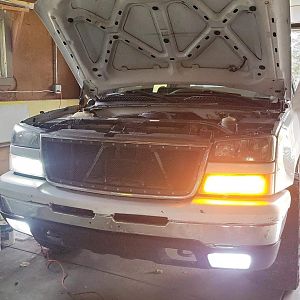
<blockquote data-quote="MultiVAC" data-source="post: 22035" data-attributes="member: 11910"><p>Took a couple extra days, but I finally finished. I've wanted to replace the clutched fan for awhile. The issues I saw when this was discussed was how to deal with going from ~10k cfm oem fan to the maybe 6000cfm dual fan setups that are usually found. Also the mechanical fan never let me down, so how reliable could I make an efan setup?</p><p></p><p>In my research I ran across this site:</p><p>[URL unfurl="true"]https://www.240turbo.com/BrushlessFans.html[/URL]</p><p></p><p>They had lots of info, measurements and wiring info which led me to choose the 2016+ Camaro SS/ZL1 Brushless fan - PN 84100128 (pwm signal is 100hz / negative )</p><p>My initial measurements showed I could barely fit two behind the big radiator, if I could find a way to build a shroud and power them. They come in at ~5600 cfm each.</p><p>I could also find several factory original fans available locally for 100-150.</p><p></p><p>I ran across this controller on ebay - <a href="https://www.ebay.com/itm/143561646769" target="_blank">https://www.ebay.com/itm/143561646769</a> which based on the documentation, one of the pwm signals it can make is 100hz / negative. Its designed to read a temperature sensor, and with a learned low and high point, it smoothly adjusts the pwm depending on where the sensor reads.</p><p>Also these fan are capable of pulling up to 50Amps each, I actually had already upgraded to a 250A alternator, but I did go ahead and upgrade the charge wire during this. </p><p>Put a pair of 120A resettable breakers on order (based on temperature degradation chart - 200F ~ 90-80A)</p><p></p><p>With these components, the idea was to have a bit of redundancy, if one fan, controller, or breaker blows I should still have the other.</p><p>I sourced a big piece of steel from a local supplier, 48x36" 10ga. I was wishing I had much thinner steel at times, but I ended up running several self taping screws for things, so that was nice.</p><p></p><p>I trimmed one fan all the way down to see the final dimensions, then I did a rough cardboard template, made some measurements, then did a sketch in Autocad, measured my cuts and bends. That got me about 90% of the way. I had to add clearance for the upper radiator hose, then I had to add a tilt backwards to clear the trans and engine oil lines. Got the fans mounted, then cut slots for the bypass shutters. Welded some studs for the controllers to bolt to using a 3D printed mount. Lots of crimping/soldering for wires. Tapped into ECT and AC compressor wires.</p><p></p><p>I sketched and 3D printed some seals and shims from flexible TPU so that it seals really well all the way around and so there's no chance of vibrations.</p><p></p><p>Did my first learning sequence on the controllers, I probably need to adjust the curve down a bit more, but I did about 150 miles between yesterday and today (unladen) no issues. I have a 180deg thermostat and so far they keep it right around there. AC is ice cold 24/7 compared to before, trans temps down a bit too. Freed up a bit of power. Sounds like twin turbo fan jets spinning up past 50% haha. I did notice a bit of voltage drop, all lights on, when the engine is at idle and when both fans spin up past about 60%, but it is still charging. I don't have any towing trips soon, so I'll be able to monitor things as it gets warmer for now.</p></blockquote><p></p>
[QUOTE="MultiVAC, post: 22035, member: 11910"] Took a couple extra days, but I finally finished. I've wanted to replace the clutched fan for awhile. The issues I saw when this was discussed was how to deal with going from ~10k cfm oem fan to the maybe 6000cfm dual fan setups that are usually found. Also the mechanical fan never let me down, so how reliable could I make an efan setup? In my research I ran across this site: [URL unfurl="true"]https://www.240turbo.com/BrushlessFans.html[/URL] They had lots of info, measurements and wiring info which led me to choose the 2016+ Camaro SS/ZL1 Brushless fan - PN 84100128 (pwm signal is 100hz / negative ) My initial measurements showed I could barely fit two behind the big radiator, if I could find a way to build a shroud and power them. They come in at ~5600 cfm each. I could also find several factory original fans available locally for 100-150. I ran across this controller on ebay - [URL]https://www.ebay.com/itm/143561646769[/URL] which based on the documentation, one of the pwm signals it can make is 100hz / negative. Its designed to read a temperature sensor, and with a learned low and high point, it smoothly adjusts the pwm depending on where the sensor reads. Also these fan are capable of pulling up to 50Amps each, I actually had already upgraded to a 250A alternator, but I did go ahead and upgrade the charge wire during this. Put a pair of 120A resettable breakers on order (based on temperature degradation chart - 200F ~ 90-80A) With these components, the idea was to have a bit of redundancy, if one fan, controller, or breaker blows I should still have the other. I sourced a big piece of steel from a local supplier, 48x36" 10ga. I was wishing I had much thinner steel at times, but I ended up running several self taping screws for things, so that was nice. I trimmed one fan all the way down to see the final dimensions, then I did a rough cardboard template, made some measurements, then did a sketch in Autocad, measured my cuts and bends. That got me about 90% of the way. I had to add clearance for the upper radiator hose, then I had to add a tilt backwards to clear the trans and engine oil lines. Got the fans mounted, then cut slots for the bypass shutters. Welded some studs for the controllers to bolt to using a 3D printed mount. Lots of crimping/soldering for wires. Tapped into ECT and AC compressor wires. I sketched and 3D printed some seals and shims from flexible TPU so that it seals really well all the way around and so there's no chance of vibrations. Did my first learning sequence on the controllers, I probably need to adjust the curve down a bit more, but I did about 150 miles between yesterday and today (unladen) no issues. I have a 180deg thermostat and so far they keep it right around there. AC is ice cold 24/7 compared to before, trans temps down a bit too. Freed up a bit of power. Sounds like twin turbo fan jets spinning up past 50% haha. I did notice a bit of voltage drop, all lights on, when the engine is at idle and when both fans spin up past about 60%, but it is still charging. I don't have any towing trips soon, so I'll be able to monitor things as it gets warmer for now. [/QUOTE]
Verification
Post reply
Random media
Latest posts
Y
GMT800 diagnostic and control app
Latest: YukonDenali03
6 minutes ago
Tech Discussion
Rust free state options
Latest: FW_Z71Burb
Today at 1:40 PM
Ebay / Craigslist Finds
Suburban rear window
Latest: ORVietVet
Wednesday at 9:35 PM
Exterior
Manual seat to Electic
Latest: AuroraGirl
Wednesday at 7:38 PM
Interior
M
Gear ratio
Latest: Marky Dissod
Wednesday at 12:00 PM
Engine & Performance
Members online
YukonDenali03
Forums
'99 - '06 GM Truck Modifications
Engine & Performance
8.1 super efan conversion
Top