Service airbag

FarmerTed

New Member
Joined
Aug 6, 2026
Messages
2
Reaction score
1
Location
Delaware
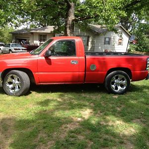
Just picked up a 2004,regular cab, long bed. Think its a WT1500 as it has power nothing.

The service airbag message appears at start up, airbag warning light on dash on and mirror displays passenger airbag inactive even though switched on. Ran my scanner and came up with B0092 which is left side front restraint sensor.

Appears to be multiple sensors on front driver seat. One on the seat belt latch, one on the seat mount rail right at the floor and maybe a weight sensor in the seat foam. All connectors are solid, no chaffed wires, no signs anything been pulled or twisted.

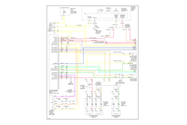
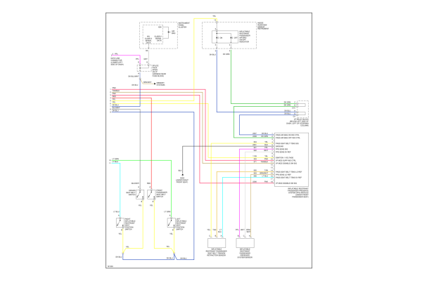
So does anyone know how test the sensors? Maybe from the master connection on the floor at the rear of the seat? Or have a wiring diagram of the SRS system?

It is worth mentioning the truck has had a right front impact at some point. Looks like only the fender was replaced. Doesn't look recent but i have no idea how long the SRS has been non functional.


Thanks in advance for your help,
Farmer Ted
 

FarmerTed

New Member
Joined
Aug 6, 2026
Messages
2
Reaction score
1
Location
Delaware
Thanks for that. Went over the harness again, both sides of truck. checked all connectors, even the ones you need to pull the seat valances to get at.

No pinched wires or signs of any ever being pinched anywhere. No chaffed wires, tape and loom intact until i statrted poking about. All connectors tight.

Guess I'll find the control module and check connectors there next.
 

AuroraGirl

Well-Known Member
Joined
Dec 24, 2023
Messages
451
Reaction score
879
Location
Wisconsin
Just picked up a 2004,regular cab, long bed. Think its a WT1500 as it has power nothing.

The service airbag message appears at start up, airbag warning light on dash on and mirror displays passenger airbag inactive even though switched on. Ran my scanner and came up with B0092 which is left side front restraint sensor.

Appears to be multiple sensors on front driver seat. One on the seat belt latch, one on the seat mount rail right at the floor and maybe a weight sensor in the seat foam. All connectors are solid, no chaffed wires, no signs anything been pulled or twisted.

So does anyone know how test the sensors? Maybe from the master connection on the floor at the rear of the seat? Or have a wiring diagram of the SRS system?

It is worth mentioning the truck has had a right front impact at some point. Looks like only the fender was replaced. Doesn't look recent but i have no idea how long the SRS has been non functional.


Thanks in advance for your help,
Farmer Ted

1786048301358.png
1786048338095.png1786048713971.png
 

AuroraGirl

Well-Known Member
Joined
Dec 24, 2023
Messages
451
Reaction score
879
Location
Wisconsin
[H3]Circuit Description[/H3]

When the ignition is turned ON, the inflatable restraint sensing and diagnostic module (SDM) performs tests to diagnose critical malfunctions within itself. When the SDM has completed the power-up mode the SDM will establish communication with the passenger presence system (PPS). The PPS will respond by commanding both the PASSENGER AIR BAG ON/OFF indicators located in the rearview mirror ON for 5 seconds. The SDM will transmit a request message to the PPS to receive the PPS verification ID. The PPS will transmit the verification ID to the SDM and the SDM will compare the ID received to data stored in memory. The SDM will also set DTC B0092 to notify the driver that the PPS has a current malfunction present. When the SDM detects that the PPS has set any one of the following DTCs, 023, 024, 033, 063, 064, or 065 the SDM will disable the I/P module deployment loop, set DTC B0092 and command the AIR BAG indicator ON. For more detailed information concerning Class 2 serial data lines, refer to Data Link Communications Description and Operation in Data Link Communications.

[H3]Conditions for Running the DTC[/H3]

Ignition 1 voltage is within the normal operating voltage range.

[H3]Action Taken When the DTC Sets[/H3]

The SDM disables the I/P module deployment loop.
The SDM commands the AIR BAG indicator ON via Class 2 serial data.
[H3]Conditions for Clearing the DTC[/H3]

The condition responsible for setting the DTC no longer exists.
You issue a scan tool CLEAR DTCs command.
A history DTC will clear once 255 malfunction free ignition cycles have occurred.
[H3]Diagnostic Aids[/H3]

DTC B0092 is an indication that the SDM has received an incorrect PPS verification ID or has lost communication with the PPS. The SDM will continue to request the verification ID from the PPS for 5 seconds. If the SDM does not receive the correct verification ID from the PPS within 5 seconds the SDM will set the DTC as current, illuminate the AIR BAG indicator, and disable the I/P module deployment loop.

Important: DTC B0092 will also set if the PPS has a current malfunction and has set any one of the following DTCs-023, 024, 033, 064, or 065. The SDM will set DTC B0092 as current and command the AIR BAG indictor ON. This is done to notify the driver of any PPS malfunctions. When DTC B0092 is present it is important to check the PPS for any current DTCs. Refer to Passenger Presence System Flash Code Procedures . If the PPS has any current DTCs address these before performing this DTC chart.


[H3]Introduction[/H3]
When the ignition is turned ON, the inflatable restraint sensing and diagnostic module (SDM) performs tests to diagnose critical malfunctions within itself. When the SDM has completed the power-up mode the SDM will establish communication with the passenger presence system (PPS). The PPS will respond by performing diagnostic tests to check for proper circuit continuity and for shorts to ground and voltage within the PPS. If the PPS detects a malfunction, the PPS will set a DTC, communicate with the SDM that a malfunction has occurred, and request the SDM to disable the I/P module deployment loop. The SDM will respond by disabling the I/P module deployment loop, setting either DTC B0092 or B0098 and commanding the AIR BAG indicator ON. The SDM sets either DTC B0092 or B0098 to notify the driver of a PPS malfunction. The DTCs that the PPS set are non-Class 2 and have to be flashed through the PASSENGER AIR BAG ON/OFF indicators located on the inside rear view mirror. The procedures below are designed to assist in the flashing of these codes. Before you start, read these procedures carefully and completely. For further information regarding the PPS refer to SIR System Description and Operation .
[H3]Passenger Presence System (PPS) Flash Code Procedure[/H3]
Important: When flashing PPS codes, the instrument panel cluster (IPC) and dash lights will begin dimming on and off. This is normal operation during the flashing procedure and does not indicate additional system faults.
  1. Empty the front outboard passenger seat.
  2. Install a scan tool.
  3. Turn ON the ignition, with the engine OFF.
  4. With a scan tool, request the passenger presence system (PPS) to flash DTCs.
  5. When the PPS receives a valid request to flash DTCs, the PPS will perform the following:
  6. 5.1. Illuminate both PASSENGER AIR BAG ON and OFF indicators located on the inside rear view mirror for 1 second.
    5.2. Turn OFF both PASSENGER AIR BAG ON and OFF indicators for 1 second.
    5.3. Flash the first number of the DTC using the OFF indicator. Count the number of times the OFF indicator flashes to obtain the first number of the DTC.
    5.4. Flash the second number of the DTC using the ON indicator. Count the number of times the ON indicator flashes to obtain the second number of the DTC.
    5.5. When the flashing procedure is initiated, the PPS will flash all current and history DTCs that are stored. After all DTCs have been flashed, to determine if the DTCs are current or history, the PPS will reflash the DTCs that are stored as current only. Any DTC that is not reflashed is stored as a history DTC.
  7. If the flashing procedure was unsuccessful repeat this procedure. Due to the communication status between the SDM and the PPS module, this procedure may have to be repeated until a successful flashing attempt has been achieved.
  8. Refer to the Diagnostic Trouble Code (DTC) List to diagnose the DTCs you have obtained.

 
Top