Miklo's 2001 Silverado 2500HD Build Thread

Mikloangelo

Well-Known Member
Joined
Oct 21, 2025
Messages
142
Reaction score
413
Location
Dallas, TX
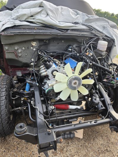
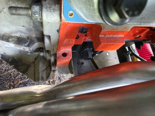
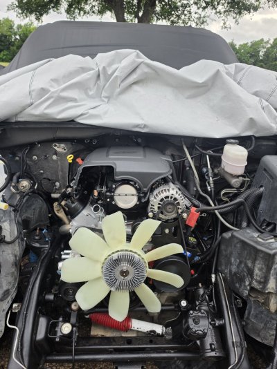
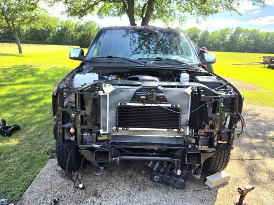
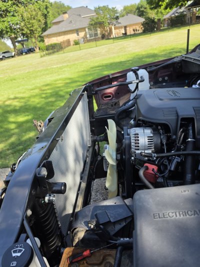
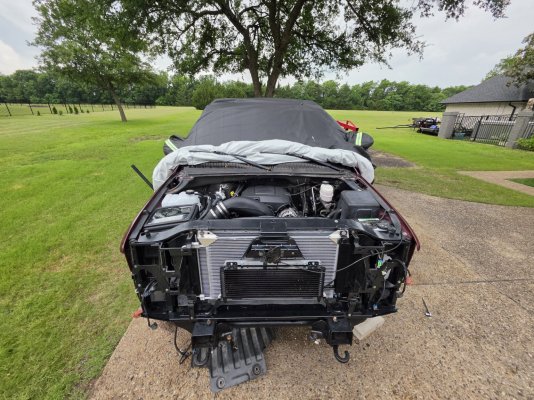
So life keeps happening and it has drastically slow me down. When I finally got a bit of time I had my neighbor help me guide in the engine and get it in place. First issue was the speed engineering 1 7/8" headers was hitting the bell housing tab on the passenger side. So I opted to smash in a tube to try and gain clearance but it still wasnt enough. So I had to trim off the tab to have ample space.
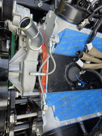
Issue number 2 is that my flexplate and torque converter had a gap past 3/8". So out came the engine partially to inspect. Found the flexplate was flipped wrong direction. Stupid me.
The next issue I had was that the TC was now binding when trying to mate the block and trans. Turns out the spacer I thought I needed was not needed. So tilt engine out again and remove spacer and reinstall flex plate. I am praying I didn't damage the internal trans pump by pushing the TC back when mating the engine.
Issue number 4 is that the gap between the flexplate and TC is beyond 3/8". Found the simple solution is one washer between the TC and flexplate will close my gap to bring me between 1/8" and 3/8".
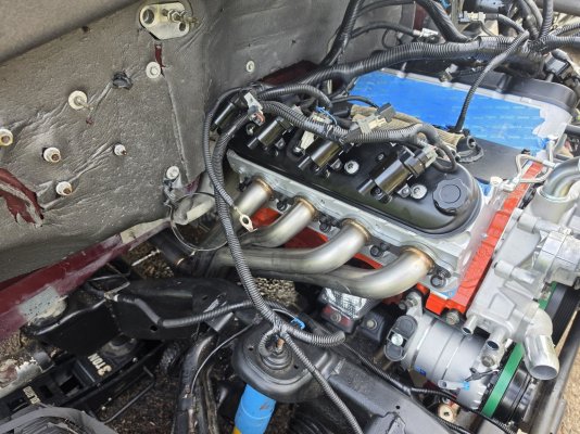
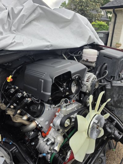
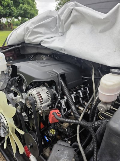
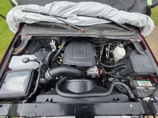
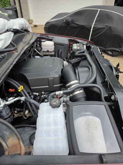
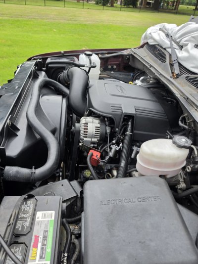
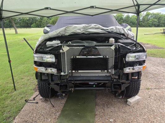
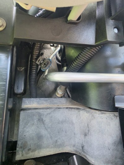
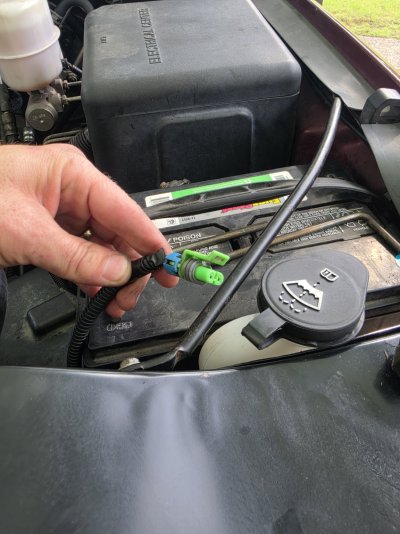
Now the motor is permanently mounted and trans is mated. Got a bit of wiring to clamp down and then throw the intake manifold on. And then start the engine bay assembly
 

Attachments

  • 20260425_175036.jpg
    20260425_175036.jpg
    448.6 KB · Views: 5
  • 20260425_175106.jpg
    20260425_175106.jpg
    442.6 KB · Views: 5
  • 20260425_175126.jpg
    20260425_175126.jpg
    319.2 KB · Views: 5

Mikloangelo

Well-Known Member
Joined
Oct 21, 2025
Messages
142
Reaction score
413
Location
Dallas, TX
While waiting for this and that before fully installing the engine. I decided to add a steam port vent in the water pump. I bought a cheap steam port vent setup and a 6 inch braided line. Tapped an 1/8NPT to -AN4 adapter on the water pump and put in another on the steam port outlet. Turned out well.
Also got around to installing my steering wheel with audio controls. I haven't hooked up any the wiring yet.
 

Attachments

  • 20260425_175044.jpg
    20260425_175044.jpg
    344.1 KB · Views: 5
  • 20260425_175214.jpg
    20260425_175214.jpg
    285.8 KB · Views: 5

stutaeng

Well-Known Member
Joined
Feb 9, 2022
Messages
858
Reaction score
2,258
Location
Dallas, TX
Did you replace the torque converter or flexplate?

The stock flexplates on the 6.0 mated with the 4L80e have a spacer from the factory.

Edit: here's a 6.0 I have in my garage with the stock flexplate...darn, I can't upload photos!
 
Last edited:

Mikloangelo

Well-Known Member
Joined
Oct 21, 2025
Messages
142
Reaction score
413
Location
Dallas, TX
Did you replace the torque converter or flexplate?

The stock flexplates on the 6.0 mated with the 4L80e have a spacer from the factory.

Edit: here's a 6.0 I have in my garage with the stock flexplate...darn, I can't upload photos!
I only replaced the flexplate. Staying with stock TC for now. I think the spacer you are referencing is the one in the center permanently fixed to the plate.
The offset of dished plate should be at or close to the OEM flat flexplate with spacer. At least that is what makes sense to me.
 

Mikloangelo

Well-Known Member
Joined
Oct 21, 2025
Messages
142
Reaction score
413
Location
Dallas, TX
Got some work done over the weekend. Got on two fenders and started routing and clamp the wires in place. I had modified the existing red battery/starter/alternator connection mounting bracket to fit my billet alternator mount. Im happy with it. It involved heating it up and bending bracket the opposite direction and then cutting away material. I should paint it but im at the stage of just getting things done.
One issue I've run into with my TBSS intake is the fuel rail system. I had to add the corvette filter to the tbss fuel rail and now my hoses are a bit too long to connect without pinching the hoses. So i have some ideas on what to do but wanting suggestions or personal experience on this.
Now I've got to connect some grounds, power steering pump hoses, install the rest if the AC system and hoses, radiator support and radiator and hoses, then start looking into the oil cooler hoses along with the transmission oil cooler hoses.
Im on the home stretch. Hoping in the next week or two I'll be ready to start it up.
Another small thing is that I would like to find an intake manifold cover for the new intake manifold. Can't seem to find the TBSS one and I dont want the sheet metal ones.
 

Attachments

  • 20260503_174043.jpg
    20260503_174043.jpg
    374.4 KB · Views: 4
  • 20260503_174049.jpg
    20260503_174049.jpg
    282.7 KB · Views: 4
  • 20260503_174150.jpg
    20260503_174150.jpg
    329.7 KB · Views: 4

Mikloangelo

Well-Known Member
Joined
Oct 21, 2025
Messages
142
Reaction score
413
Location
Dallas, TX
I thought I had seen guys mount the Corvette FP regulator on the firewall, maybe with some sort of bracket?
I've been looking at my options and this was one option ive come across. Another option is basically the same thing but just mounting it under the fuel rail and having another hose connect from the fuel filter to the fuel rail. Another option involves cut back the flexible hose to the metal line and flaring it and putting on an -AN fitting. Im opting to just relocate the filter and finding a hose with a QD on both ends to connect to the fuel rail.
 

Mikloangelo

Well-Known Member
Joined
Oct 21, 2025
Messages
142
Reaction score
413
Location
Dallas, TX
So I found the solution to the intake manifold cover with the TBSS intake manifold.
The cover goes to alot of GM vehicles from 2007-2019. The part number is GM12625893.

It attaches to a plate on top of the intake manifold. Part number GM15858430. The plate is a bit different than the OEM plate on the original intake manifold. Its shorter and doesnt have holes to hold the throttle body cables in place. Not a big deal I'll come up with something to hold them in place if I feel its needed.

Other parts you'll need are the studs that screw into the intake manifold that hold the cover in place via rubber grommets on the under side of the cover. You need two. Part number GM11609319.

If you have throttle body cables you'll need to trim back the rear driver's side portion of the intake manifold cover about two inches so the cables can tuck in under the cover.
I like this better than the sheet metal covers and makes it stock looking. It isnt a new idea by any means but no one has listed out what is needed to get it done.
 

Attachments

  • 20260508_175548.jpg
    20260508_175548.jpg
    305 KB · Views: 3
  • 20260508_175551.jpg
    20260508_175551.jpg
    334.7 KB · Views: 4
  • 20260508_175556.jpg
    20260508_175556.jpg
    299.1 KB · Views: 3
  • 20260508_175618.jpg
    20260508_175618.jpg
    464.8 KB · Views: 3
  • 20260508_175709.jpg
    20260508_175709.jpg
    493.7 KB · Views: 2
  • Screenshot_20260508_184428_eBay(1).jpg
    Screenshot_20260508_184428_eBay(1).jpg
    61.1 KB · Views: 3
Last edited:

Mikloangelo

Well-Known Member
Joined
Oct 21, 2025
Messages
142
Reaction score
413
Location
Dallas, TX
I had some time today to knock out a few things on the truck today. I started off with connecting grounds to the block and heads. Then tackled the C5 fuel pressure regulator that was pinching my OE hoses when the FP regulator was connected directly to the fuel rail of the TBSS intake. So i found a 05-13 Chevy Corvette C5/C6 fuel pump feed hose line, that allows me to mount it a bit differently but still be hidden under the new intake cover. Though I did trim a bit more of the cover to compensate.
Overall im satisfied with the way it turned out.
 

Attachments

  • Screenshot_20260516_184911_eBay.jpg
    Screenshot_20260516_184911_eBay.jpg
    39.5 KB · Views: 3
  • 20260516_143425.jpg
    20260516_143425.jpg
    436.7 KB · Views: 3
  • 20260516_152103.jpg
    20260516_152103.jpg
    348.5 KB · Views: 3

Mikloangelo

Well-Known Member
Joined
Oct 21, 2025
Messages
142
Reaction score
413
Location
Dallas, TX
I also tackled mounting the radiator support. I first pieced the whole assembly together. Which includes the radiator, AC condenser, and a new transmission oil cooler. To mount the new transmission oil cooler i used some 1 inch aluminum square tubing and cut it to fit, picked up the riv-nuts for the cross support and drilled new holes in the upper support area to mount the upper side of the oil cooler.
I started the AC line and air dryer installation as well. Im missing the main line that goes from the dryer to the condenser but its on the way along with some nuts.
I also started connecting coolant hoses and heater core hoses to the radiator and water pump. I spent the time and got all the metal dorman fittings for the heater core and water pump tee fitting.
 

Attachments

  • 20260516_164106.jpg
    20260516_164106.jpg
    541.4 KB · Views: 2
  • 20260516_164140.jpg
    20260516_164140.jpg
    310 KB · Views: 2
Last edited:

Mikloangelo

Well-Known Member
Joined
Oct 21, 2025
Messages
142
Reaction score
413
Location
Dallas, TX
With the radiator support in place it allowed me to route the front end wiring harness in its final resting place for the most part. Still a few things to tidy up first like getting the correct headlight brackets. Mine were very close but the blinker assembly mounting off and I couldn't put them on. So now I've got to order another set.
While routing things in place I cam across this one connector. I cant seem to find where it goes? Can anyone help me put here. Its around the bottom side of the compressor area
 

Attachments

  • 20260516_164800.jpg
    20260516_164800.jpg
    240.2 KB · Views: 3

stutaeng

Well-Known Member
Joined
Feb 9, 2022
Messages
858
Reaction score
2,258
Location
Dallas, TX
With the radiator support in place it allowed me to route the front end wiring harness in its final resting place for the most part. Still a few things to tidy up first like getting the correct headlight brackets. Mine were very close but the blinker assembly mounting off and I couldn't put them on. So now I've got to order another set.
While routing things in place I cam across this one connector. I cant seem to find where it goes? Can anyone help me put here. Its around the bottom side of the compressor area
That doesn't go to your AC compressor? I seem to recall some of the earlier GMT800s had 2 connectors?
 

Mikloangelo

Well-Known Member
Joined
Oct 21, 2025
Messages
142
Reaction score
413
Location
Dallas, TX
Also, I have a goal of removing the Quick disconnect lines from the transmission cooler side and the engine oil cooler side on the radiator. This will allow me to convert them to -AN fittings. 6AN on the transmission side and 8AN on the oil side. The trans side fittings are 5/8-18 inverted flare threads on the radiator (i believe). And on the oil side it is a M20x1.5 thread. The oil fitting is a bit different and havent seen any solutions online yet. I have a path im exploring but i need to find the correct adapter. The one I found is close but the AN adapter i have is incorrect. Will keep everyone updated. Im also considering going to a local machine shop just to have it made.
 

Attachments

  • 20260516_193609.jpg
    20260516_193609.jpg
    386.1 KB · Views: 1
Last edited:

Mikloangelo

Well-Known Member
Joined
Oct 21, 2025
Messages
142
Reaction score
413
Location
Dallas, TX
That doesn't go to your AC compressor? I seem to recall some of the earlier GMT800s had 2 connectors?
Figured it out. It goes to the back side of the compressor to the high pressure cut out switch. The compressor from UAC came with a blank off plug, so now I need to buy one and install it, which will be easier said than done.
 

Mikloangelo

Well-Known Member
Joined
Oct 21, 2025
Messages
142
Reaction score
413
Location
Dallas, TX
Took a few hours today to do a few things on the truck. Just messing with the steering hose routing and some electrical. Decide to mock up the fan shrouds, upper radiator hoses, battery, and my new intake. I needed a bit of motivation to hurry up and finish, and this pretty much does it.
At this point its only lacking transmission and engine oil cooler hoses that i need to make, an AC line, a few AC sensors, and fluids. Then will tow it to a tuner for the break in and tune.
Another advantage of mocking things up is it gets a few big boxes out of the way of my garage which makes the wife happy.
 

Attachments

  • 20260517_122736.jpg
    20260517_122736.jpg
    349.9 KB · Views: 1
  • 20260517_122816.jpg
    20260517_122816.jpg
    256.9 KB · Views: 1
  • 20260517_122808.jpg
    20260517_122808.jpg
    284.8 KB · Views: 1
  • 20260517_122801.jpg
    20260517_122801.jpg
    445.1 KB · Views: 1
  • 20260517_122757.jpg
    20260517_122757.jpg
    529.7 KB · Views: 1

Mikloangelo

Well-Known Member
Joined
Oct 21, 2025
Messages
142
Reaction score
413
Location
Dallas, TX
Finally got my AC line in and put it on. AC is complete minus charging the system, since i actually need the engine running for it.
I ditched the oil line conversion idea since I was having difficulty sourcing the correct adapter, so i went back with the OEM engine oil cooler lines. For now anyhow.
I made all the transmission cooler lines, just waiting on an adapter to complete it.
I put in the high pressure cut out switch on the back side of the compressor through the passenger side wheel well. What a pain, but I got it done. Also made sure all the hoses and lines are all tight and/or have clamps on. Hoping to take it to the tuner this week.
 

Mikloangelo

Well-Known Member
Joined
Oct 21, 2025
Messages
142
Reaction score
413
Location
Dallas, TX
I put on my new headlights and blinker and came across a few connectors that im not sure where they go.
First I have an extra socket hanging around the blinker assembly area. Are these extra? Not sure where they could go.
Another connector is a green connector that i havent a clue where it goes. It can reach to the center if the radiator support or the top on the head light area on the driver's side. Its not the airbag sensor since I have that hooked up.
Another connector is a small 2 pin connector on the passenger side. Its not the horn, and doesnt go to a light. Is there a sensor on the AC line going to the AC condenser that im missing?
Any help is appreciated
 

Attachments

  • 20260525_165611.jpg
    20260525_165611.jpg
    450.1 KB · Views: 2
  • 20260525_164817.jpg
    20260525_164817.jpg
    295.3 KB · Views: 2
  • 20260525_165355.jpg
    20260525_165355.jpg
    269.3 KB · Views: 2
  • 20260525_165350.jpg
    20260525_165350.jpg
    300.5 KB · Views: 2
  • 20260525_164024.jpg
    20260525_164024.jpg
    313.2 KB · Views: 2

Latest posts

Members online

Top